![]()
Corella RevC User Reference Manual
This document is available in PDF format : (492K)
- Functional Description
- Quick Setup
- Hardware
- Absolute Maximum Ratings
- Electrical Characteristics
- Pinout
- Mechanical Outline
- Low Power mode
- Compatibility with Popular Development Systems
- Data
- Serial Port Set Up
- Corella Packet Format
- AT Commands
- AT (Attention)
- AT+STATUS
- AT+SEND
- AT+VERSION
- AT+ID
- AT+DIAGNOSTICS
- AT+LEDS
- Serial Communication Example
- AT
- Status
- Send Packet
- Version
- Diagnostics
- ID
- LEDS
- Application Examples
- Raspberry Pi Setup
- Arduino Setup
1. Functional Description
The Corella Low Power Wide Area Network (LPWAN) module allows developers to connect a range of IoT devices to the Taggle network.
The Taggle network is an LPWAN solution based on world leading Australian developed technology operating in the 916-928MHz Low Interference Potential Device (LIPD) class licence band, which has been developed by Taggle Systems to provide one of the lowest cost, lowest power, longest range, and highest capacity LPWAN solutions available. The Taggle network is based on one-way transmissions from endpoint nodes to the Taggle receiver network, and is particularly well suited to battery powered endpoint applications with low data rate requirements, such as automatic meter reading, wireless sensors for smart agriculture and environmental monitoring, and cost sensitive smart city applications.
Corella is based on the popular XBee module format, and provides a single serial port with a simple “AT” command style interface to allow rapid integration of the module into both lab prototypes and volume production IoT devices. The module has a single radio transmit output via an SMA connector, and can be supplied with a 2dBi ½ wave dipole antenna to enable rapid connection to the Taggle network.
All receive functions are handled seamlessly by the Taggle network, with the user’s receive data presented via a custom web portal. A range of data plans are available depending on the number of endpoints connected to the Taggle network and the frequency of messages per endpoint.
2. Quick Setup
- Firmly screw on antenna.
- Connect device through correct pins, refer to section 3.3
- When powered, observe the green power LED indicating a power connection.
- Press TX test button to transmit a Taggle test packet.
- Observe the flashing Blue LED which indicates payload is transmitting and should deactivate after roughly 10 seconds.
- Once the blue LED has stopped flashing this indicates the transmit period has concluded and Corella is now ready to transmit another packet. Note that while the blue LED is flashing Corella's Tx functionality is withheld and any send commands will not be processed.
- Note: Wait time remaining can be queried through serial communication using simple AT commands outlined in Section 5, AT Commands.
- Go to the Corella Data Portal and input the user name/Taggle ID and password provided with the Corella unit.
- Check to confirm your first data packet. This may take up to 15 seconds to process.
3. Hardware
3.1. Absolute Maximum Ratings
 The revision C Corella module is compatible with 3.3V systems only.
Connection to 5V systems such as Arduino or Beagle Bone will require an interface shield to provide appropriate IO level translation and power supply regulation.
| Symbol | Parameter | Min | Max | Unit |
|---|---|---|---|---|
| VDD | Supply Voltage | 3.8 | V | |
| DIN | Data input | -0.3 | VDD + 0.3 | V |
| DOUT | Data output | -0.3 | VDD + 0.3 | V |
| RST | Reset input | -0.3 | VDD + 0.3 | V |
3.2. Electrical Characteristics
| Symbol | Parameter | Min | Nom | Max | Unit |
|---|---|---|---|---|---|
| VDD | Supply Voltage | 2.8 | 3.3 | 3.8 | V |
| VIL | Voltage input low | 0.3* VDD | V | ||
| VIH | Voltage Input High | 0.7* VDD | V | ||
| VOL | Voltage output Low | 0.3* VDD | V | ||
| VOH | Voltage output High | 0.75* VDD | V | ||
| TAMB | Operating Temperature Range* | -20 | 25 | 70 | °C |
| IA | Awake current | 2.2 | 2.4 | mA | |
| ITx | Transmit Current | 95 | 110 | mA | |
| Iq | Quiescent Current | TBA | 6 | uA |
* Electrical characteristics measurements were taken in low power mode refer to section 3.5. Nominal sleep current in default mode is approximately 1.5mA
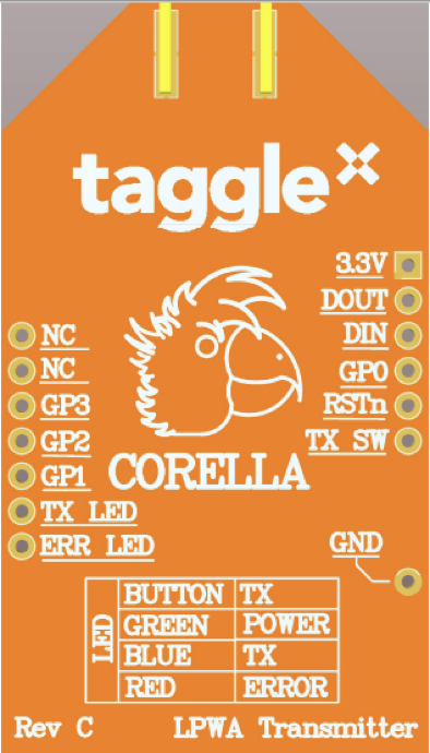
3.3. Pinout
| PIN | SYMBOL | DESCRIPTION |
|---|---|---|
| 1 | 3V3 | Power Supply Input |
| 2 | DOUT | Data Output. |
| 3 | DIN | Data Input. |
| 4 | None | Not Connected |
| 5 | RSTn | Reset Input Active Low |
| 6 | TX_SW | Connected to Push button – active low |
| 7-9 | NC | Not Connected |
| 10 | GND | Ground |
| 11 | NC | Not Connected |
| 12 | ERR_LED | Error LED, activates on command error |
| 13 | TX_LED | Transmit LED activates on reset and blinks for duration of transmit. |
| 14 15 16 |
GP0 | General purpose Input pins. Not supported in Revision C |
| 16-20 | NC | Not Connected |
3.4 Mechanical Outline
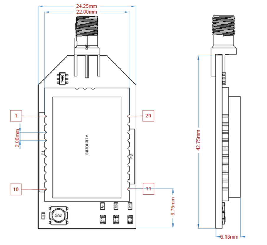
Figure 2 Corella Dimensions
3.5. Low Power mode
The default configuration will nominally consume 1.5mA during sleep mode. The main power draw is from the green power LED and the voltage overload protection circuit. These features can be disabled by removal of the two jumper resistors shown below. This will significantly reduce the power consumption resulting in a nominal sleep current of approximately 2uA.
Removal of the jumper resistor J1 shown in Figure 3 will deactivate the green power led and reduce Corella sleep current to approximately 95 uA. Deactivating the flashing red and blue LEDs can be achieved through AT commands, referred to in section 5.7 AT+LEDS .
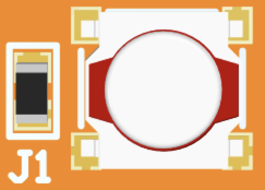
Figure 3 - Power LED resistor
3.6. Compatibility with Popular Development Systems
| Device | Compatible | Compatible Shields |
|---|---|---|
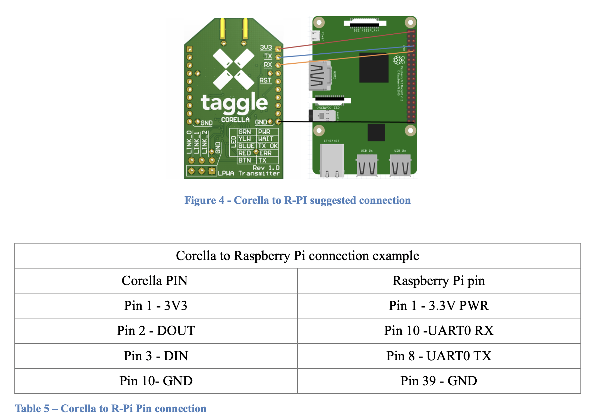
| Raspberry Pi | Yes, can be connected directly with wires. View example in section 7.1 Raspberry Pi | None yet that have been verified by Taggle Systems. |
| Arduino Uno | Not directly, Arduino uses TTL (5V logic levels) which may damage the Corella module. Voltage translation is required. View section 7.2 Arduino | The Taggle Corella Arduino shield converts all input voltage levels to allow full compatibility between the Arduino Uno and the Corella Module.
|
4. Data
4.1 Serial Port Set Up
Rev A module: 9600 Baud, no parity, 1 stop bit, no flow control
(9600 Baud - 8N1)
4.2 Corella Packet Format
| Field | PacketID | User Payload | |||||||||||
|---|---|---|---|---|---|---|---|---|---|---|---|---|---|
| Byte | 0 (4 bits) | 1 | 2 | 3 | 4 | 5 | 6 | 7 | 8 | 9 | 10 | 11 | 12 |
User Payload • Fixed 12 Bytes of User Data (Using AT+SEND command).
Packet ID • ASCII character between '1' and '9'.
5. AT Commands
- Commands and response all terminate with :
\r\n - Commands which are incorrectly formatted will return :
ERROR - Commands that do not complete in 10 seconds will return :
TIMED OUT
Supported Commands:
| 5.1. AT (Attention) | |
| ATTENTION | |
|---|---|
| Commands | Response |
AT
|
OK
|
| 5.2. AT+STATUS | |
| STATUS | |
| Command (QUERY) | Response |
AT+STATUS? \r\n
|
WAIT [SECONDS] SEC\r\n
|
| 5.3. AT+SEND | |
| SEND | |
| Command (SET) | Response |
AT+SEND=[<PACKET ID>,<DATA>]
|
OK |
| 5.4. AT+VERSION | |
| VERSION | |
| Command (QUERY) | Response |
AT+VERSION?
|
TAGGLE SYSTEM\r\n
|
| 5.5. AT+ID | |
| TAGGLE ID | |
| Command (QUERY) | Response |
AT+ID?
|
[TAGGLE ID]\r\n
|
| 5.6. AT+DIAGNOSTICS | |
| DIAGNOSTICS | |
| Command (QUERY) | Response |
AT+DIAGNOSTICS?
|
AT+DIAGNOSTICS=OK
|
| 5.7. AT+LEDS | |
| CONFIG | |
| Command (SET) | Response |
AT+LEDS=[STATE]
Default State is on.
|
LEDS [STATE]
|
6. Serial Communication Example
The following is a record of serial communications conducted using a terminal interface.6.1. AT
[TX] - AT<CR><LF>
[RX] - OK<CR><LF>
6.2. Status
[TX] - AT+STATUS?<CR><LF>
[RX] - OK<CR><LF>
6.3. Send Packet
[TX] - AT+SEND=1,0123456789AB<CR><LF>
[RX] - OK<CR><LF>
[TX] - AT+SEND=1,0123456789AB<CR><LF>
[RX] - WAIT_07_SEC<CR><LF>
6.4. Version
[TX] - AT+VERSION?<CR><LF>
[RX] - TAGGLE_CORELLA<CR><LF>
       H.W=REV_C<CR><LF>
       F.W=2.1.31<CR><LF>
6.5. Diagnostics
[TX] - AT+DIAGNOSTICS?<CR><LF>
[RX] - MAX_TEMP=32<CR><LF>
       MIN_TEMP=26<CR><LF>
       BATTERY=3.81V<CR><LF>
6.6. ID
[TX] - AT+ID?<CR><LF>
[RX] - 130123<CR><LF>
6.7. LEDS
[TX] - AT+LEDS=ON<CR><LF>
[RX] - LEDS ON<CR><LF>
[TX] - AT+LEDS=OFF<CR><LF>
[RX] - LEDS OFF<CR><LF>
7. Appplication Examples
7.1 Raspberry Pi Setup
For detailed information and existing Library refer to the Corella + Raspberry Pi guide.
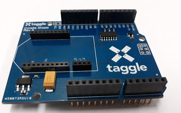
7.2. Arduino Setup
For detailed information and existing Library refer to the Corella + Arduino guide.
The Corella Arduino Shield is asymmetrical and will only fit properly using the correct orientation.
The Corella should be fitted to the shield as shown with the antenna SMA connector overhanging the edge of the board.
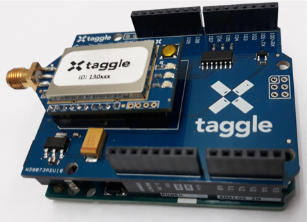
Figure 6 - Arduino fitted to Corella Arduino Shield
About Taggle Systems
Taggle is an Australian based and owned developer of Low Power Wide Area (LPWA) radio technology offering low-cost, low-power, long range communications for many types of sensors and devices.
With a rapidly expanding international network, we service high-rise and urban centres, regional utilities, remote communities and farm monitoring. We work with our customers to deliver tailored solutions.
The Corella project enables experimentation, innovation, small-scale or specialized projects to be implemented without fuss or large investment.